Freehand Drawing

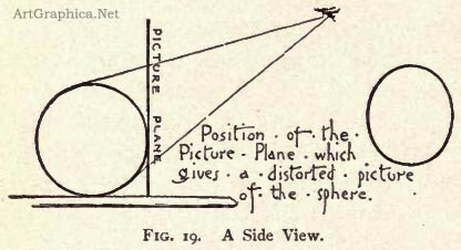
Fig. 19 is a side view representing the sphere, the eye, and a vertical picture plane touching the sphere. The visual rays from the sphere to the eye form a cone, and Fig. 19 shows that this cone of rays is intersected obliquely by the vertical picture plane. The cone is a circular cone, -- that is, if it is cut by a plane at right angles to its axis the sections will be a circle; and by geometry we know that if it is cut by a plane not at right angles to the axis, as is the picture plane in the figure, the section will be an ellipse. This elliptical section is the picture of the sphere on the vertical picture plane, and the ellipse covers the sphere when the eye is at the station-point,--that is; the ellipse appears a whose image coincides with the circular image produced in the eye by the sphere. When the eye is in the proper position for viewing Fig. 18, it appears a circle, and if the eye is placed at a point about 4 1/4" from the paper and in a perpendicular to the page erected at the point marked CV, the ellipse of Fig. 18 will be seen obliquely and foreshortened into a circle.[1] In order to see the figure when the eye is so near, it will be necessary to make a circular hole about 1/8” in diameter in a card and view the drawing through this hole, which serves as the station-point.
This illustrates the important fact that to create the same image in the eye that the object does, any perspective drawing must be seen from one fixed point, and if seen from any other point the perspective drawing will appear distorted, and create in the eye a very different image from that which the object itself will form.
Fig. 20 represents a sphere and a cube placed upon a horizontal surface below and at the left of the eye, -- the camera. This picture does not cause the reader to think of a sphere, but it does create the idea of a cube, because cubes have been represented in this way so generally that the average person accepts the drawing as a satisfactory representation of the cube. But it is evident that if the inclined ellipse which represents the sphere, is a distortion, the representation of the cube below it must be as much distorted, and actually it is more distorted than the ellipse. If the eye is placed at the station-point, which for Fig. 20 is about 5 1/8” from the paper and in a perpendicular to the page erected at the point marked CV, the drawing will be seen obliquely and so foreshortened that the ellipse will appear a circle, and the representation of the cube will cause the same image in the eye that the cube does. Figs. 18 and 20 are distorted because they are made on a vertical picture plane through which the visual rays pass obliquely.
* 1. These letters are often used to designate the centre of vision, or the point on the picture exactly opposite the eye of the spectator. At this point all lines perpendicular to,the picture plane vanish.
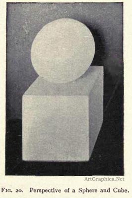
FIG. 20. Perspective of a Sphere and Cube.
Fig. 21 is a side view representing the sphere situated as in Fig. i8 with a picture plane touching the sphere, and so inclined as to be perpendicular to a line from the spectator's eye to the centre of the sphere. This line is the central visual ray and the axis of the circular cone formed by the visual rays. Since this cone is intersected by a picture plane which is perpendicular to its axis, the section of the cone --that is, the perspective or picture of the sphere --is a true picture of the object and is similar in its form to the picture formed by the sphere in the eye.
The picture of Fig. 21 is a circle, and differs from that of Fig. 18 in a very important point ; for when Fig. 18 is correctly seen the eye must be at one fixed point. When thus seen it creates in the eye a circular image, but the picture of Fig. 21 may be seen from any point situated in a perpendicular to the picture erected at its centre, and the image produced in the eye will be a circle, without regard to the distance of the eye from the paper.
We must decide that the drawing, Fig. 21, which represents the sphere by a circle is preferable to the drawing, Fig. 18, which represents the sphere by an ellipse ; for though Fig. 18 may be seen so as to create a circular image in the eye, there is little chance of this occurring, and practically, no person, whether artist or not, would ever think of drawing anything but a circle to represent a sphere.
Perspective drawings are distorted as shown because any person who looks at a drawing or picture naturally holds it in the hand, so that its surface is at right angles to the direction in which it is seen ; or, if it is a framed picture, the person stands directly in front of it, and so that its surface is not foreshortened. If a picture is too large to be taken in at a glance, the eye is moved so that when any part is seen it is looked at from a direction practically perpendicular to the surface. A person looking at a large canvas naturally places himself in front of the left part when he is studying figures or other details represented in this part ; and in the same way he studies figures or detail at the extreme right of the canvas by standing directly in front of this part. Of course he obtains his impression of the effect of the whole picture when he is in front of the centre of the picture, but when in this position he does not study the extreme parts for detail because he has unconsciously acquired the habit of looking at a picture so that its surface is not foreshortened. Whether the eye moves or not in studying a large canvas is a question of no importance, for the artist never draws a figure distorted, as Figs. i8 and 20 are distorted, in order that it may look right when the picture is seen from one fixed point near the canvas; and he never makes a drawing which he intends to be seen obliquely from a point in a perpendicular to the picture which falls outside the limits of the drawing.
If the perspective drawings, Figs. 18, 19, and 2o, are looked at naturally they will give very false ideas of the appearances of the objects they represent. In order that Fig. 18 give the impression of a circle, the page must be held vertically and so that the whole drawing is below the eye. If Fig. 20 is to give the right impression, the page must be held vertically and so that the whole drawing is below and at the left of the eye, and it is evident that, naturally, no person would ever make a free-hand drawing which must be viewed so unnaturally.
The cube shown in Fig. 20 is represented by a scientific perspective drawing in Fig. 22. This drawing will give the same image in the eye that the cube does if it is seen from a point about 9" from the paper erected at the point marked CV The image produced in the eye by thus viewing Fig. 22 will be found to be practically the same as that given by looking at Fig. 23 from a perpendicular to the page erected at the centre of the drawing ; and it is evident that the perspective, Fig. 22, when it is seen as it generally will be, is as much a distortion as the ellipse of Fig. 18 which represents the sphere.
To create the same image in the eye as the object, Fig. 20 must be seen from a point about 5 1/8”" from the paper, and this may cause the student to think the drawing more distorted than perspective drawings generally are. But this is not the case, for if the dimensions of the drawing are made twice as great, the distance of the eye will be about 10 1/4", and if the drawing is made three times the size, the distance of the eye will be increased proportionately and will be a normal distance, while the drawing is as distorted as Fig. 20 because it must be seen obliquely.

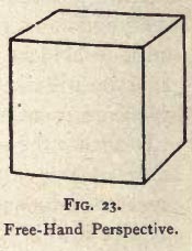
Fig. 22 is a scientific perspective which distorts much less than such drawings generally do for the distance of the eye is greater in proportion to the size of the drawing than is often the case, so that there will generally be a greater difference between perspective drawings and model drawings than between Figs. 22 and 23.
Fig. 24 is a perspective drawing, upon a vertical plane; it represents two horizontal circular plinths, A and B, A being directly in front and B placed at the right. This drawing represents the circles of the plinth at the left by horizontal ellipses. The eye sees these circles as horizontal ellipses, and the part A is a true picture, except that its height is too great.
The horizontal circles of plinth B are represented by inclined ellipses, and so, to give the right effect, the drawing must be seen from a point opposite, CV, and about 4 3/4" from the paper. If seen naturally the part B (does not form a true picture of the object, and horizontal circles should not be represented by inclined ellipses unless they are tangent to squares, or so placed that they cannot be represented as they appear, and give the correct impression of their position. The plinths A and B are of the same size, but it will be noticed that the perspective of B is wider than that of A.

It appears that all depends upon the position of the station-point from which the drawing is to be seen, and that any drawing which requires to be foreshortened in order to look like the object is not a satisfactory representation. The artist naturally draws what will create a true picture in the eye when the drawing is seen perpendicularly, and any drawing of a single object which requires to be seen obliquely, cannot be accepted as the best picture of the object. The best picture of any object must be the one which, when not foreshortened, causes in the eye an image practically like that which the object itself would produce.
Fig. 2 1 shows that the picture plane which gives a picture which is similar to the image in the eye must be at right angles to the direction in which the object is seen. In the case of the sphere below the eye, as in Fig. 2r, a circle is given upon the inclined picture plane, and this circle, when viewed naturally, causes the same image in the eye that the sphere does ; but it is possible to obtain a true picture on a plane at right angles to the direction in which an object is seen which will not when viewed naturally, produce a satisfactory impression of the object.
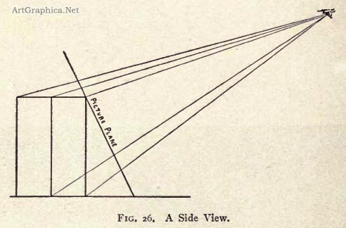
Fig. 25 is from a photograph of a vertical square prism below the eye, the picture plane (the negative) being at right angles to the direction in which the prism was seen as illustrated by the side view, Fig. 26. The side view shows that the lower ends of the vertical edges are farther from the eye than the upper ends; these vertical edges must then appear to converge downwards, just as Fig. 25 represents them. Fig. 25 is a plane perspective upon an inclined picture plane instead of a vertical plane. When the eye is at the station-point, which for Fig. 25 is about 4" from the paper, and in a perpendicular to the page erected at the centre of the drawing, and when the drawing is inclined, as shown in Fig. 26,. its lines will exactly cover the edges of the object, and will, of course, cause in the eye the same image that the object does; but if the eye is placed nearer the paper or at a greater distance, or if the paper is not at the proper inclination, the lines of Fig. 26 will not cover the edges of the object, and the drawing will give the impression of an inclined prism instead of a vertical one. This drawing is just as objectionable as Figs. 18 and 20, for it requires to be seen from one fixed point if it is not to give the impression of inclined lines in nature.
If the plane perspective drawing is made upon a vertical plane, the vertical edges will be represented by the vertical lines of Fig. 27; but to give the right impression of the relative height and width of the appearance, this drawing must be foreshortened by being seen from a point about 4 1/8" from the paper and in a perpendicular to the page erected at CV. If looked at naturally the image created is too high, but it gives the right impression of the form and position of the object, and is more satisfactory than Fig. 25. We see that in the case of the prism, an exact perspective drawing on an inclined plane is not as satisfactory as one upon a vertical picture plane, for though giving the proportions correctly, it does not give the impression of a vertical object. Neither Fig. 25 nor Fig. 27 is satisfactory or would be made by the artist, who would represent the vertical edges by vertical lines, but would give the impression of the relative width and height by representing the visual proportions of the object. The artist works by feeling and by eye more than by measurement, but, in theory, the width to be represented by means of vertical lines would be the average of the widths at top and bottom of Fig. 25, -- that is, the width would be measured at the centre of the object for comparison with the height, and the resulting drawing, Fig. 28, is like Fig. 27, but not so high.
The artist, as he draws any single object, does not think of a picture plane, but simply feels the visual proportions and represents the object so as to create a satisfactory impression of it and its position, and he represents vertical edges by vertical lines. Vertical edges appear to vanish just as much as do horizontal retreating edges, but they are not so represented for the reason explained. With this exception any single object causing small visual angles should be represented just as it appears, and its appearance is given upon a picture plane which is at right angles to the direction in which the object is seen. If the object is above the eye, the plane will incline at the top toward the eye ; if the object is on the level of the eye, the plane will be vertical, and wherever the object is situated with reference to the spectator, whether in front, at the right, or at the left, the picture plane will be perpendicular to the direction in which the object is seen.
Generally, objects are so little above or below the level of the eye that a perspective, made upon a vertical plane at right angles to a horizontal line from the eye to a point just over or under the object, will be satisfactory, and if an object is far enough from the level of the eye to cause its perspective on this vertical plane to be much too high, the artist's drawing may be supposed to be made upon the vertical plane, and corrected by changing the height of the drawing to agree with the apparent height of the object. The question of the plane of the drawing is, however, of little importance when single objects are studied, for pupils should then always be taught to give the actual visual proportions, to represent vertical edges by vertical lines, and to take any measurements of proportions with the measuring rod always at right angles to the visual rays ; and it is not necessary for them to think of picture planes, vertical or inclined.
All single objects causing small visual angles should generally be represented just as they appear except as to the convergence of vertical edges, but when *here are several objects to be represented in the same drawing the problem is more complicated.
A row of three equal boxes placed in a straight line is represented by the Figs. 29, 3o, and 31. Fig. 29 represents the actual appearance of the left box, Fig. 3o that of the central box, and. Fig. 31 that of the right-hand box. Each drawing is a separate and complete picture, and should be studied when the other figures are covered by pieces of paper, and with the eye in a perpendicular to the drawing. When Fig. 29 is thus studied it gives the best impression of the appearance and position of the left box ; when Figs. 29 and 31 are covered, and Fig. 3o is seen perpendicularly, it gives the best representation of the central box ; and when Figs. 29 and 3o are covered, and Fig. 31 is seen perpendicularly, it gives the best impression of the box at the right. Box A is farther from the eye than box B, and, consequently, its vertical edges appear shorter than those of box B, and their ends appear respectively higher than those of the edges of box B. The ends of the long edges of the box A are unequally distant from the eye, and by Rule 6 they must appear to vanish; and by Rule 17 we find that not one of the three visible faces of the box A can appear its real shape. The same facts govern the appearance of box C, Fig. 31 ; and it is evident if we draw each of the boxes as it is seen, arid with its corners relatively higher than the corresponding ones of box B, that we cannot look at the drawings, Figs. 29, 30, and 31, as one picture, for if the three are seen at one time, the impression of boxes arranged in a curved line is given.
These figures illustrate the fact that when objects, or an object, cause large visual angles (angles over 30°), we cannot draw the appearance of each object, or of each part of the one object, and produce a satisfactory picture, for the picture will give the appearance of the objects and not their relative positions. It is much more important that the one drawing, Fig. 32, which represents the three boxes, give the impression of boxes arranged in a straight line, than that the part representing the box at the left, or that at the right, be a true picture of the box ; therefore, the artist who represents in one drawing the three boxes will do so by the use of horizontal straight lines, as in Fig. 32.
The boxes, A and C are farther from the eye than box B, consequently, their front faces are foreshortened horizontally, so as to appear narrower than that of B. In Fig. 32 the artist would generally represent the three faces of equal width, and he would, also, probably omit the representation of the foreshortening of the spaces between the boxes. The three front vertical faces are below the eye, and so foreshortened vertically ; this foreshortening would not be represented in Fig. 32 unless the horizontal foreshortening is given, and generally, the artist would make for Fig. 32, an exact parallel perspective drawing, as illustrated and explained under Fig. 34.
Figs. 29, 30, and 31, when looked at incorrectly as one picture, give the effect of curved lines, and lead one to question if straight lines in nature do not appear curved. It is a fact that straight lines do appear curved, even when they are short. The line connecting the front upper edges of the three boxes, Figs. 29, 3o, and 31, will prove this, if we apply Rules 6 and 9. Thus, point r is the nearer end of line 1-2, which must, by Rule 6, appear to incline upward to the left; and point r is the nearer end of line T-3, which must then appear to incline upward to the right. But the line 2-1-3 appears horizontal at I ; there is certainly no angle formed at this point, and it is evident that the change from the level of r to that of 2 and 3 must be gradual, -- must be, in fact, a regular motion which produces in the eye the effect of a curve ; but the mind reads this curve in the eye as the picture of a straight line, and refuses to think of a straight line, when the three drawings, Figs. 29, 30, and 31, are looked at as one picture.
It is difficult to believe that straight lines appear curved, but this appearance is always given by long straight lines which the mind does not know to be straight. At sunset the shadows of the clouds extend in straight lines, which are often practically horizontal with reference to any observer. These shadows appear as bands of dark, separated by the bright bands of the unobscured rays of sunlight, and both dark and light bands are seen radiating from the sun, and becoming wider and wider as they recede from it and approach the spectator. Sometimes these cloud shadows may be seen extending to directly overhead, and sometimes they extend beyond the spectator toward the east, when they seem to converge opposite the sun, as they do in the west at the sun. When the impression of these lines extending from overhead toward both the west and the east is received, the effect of curvature is realized, for the mind does not think of these bands of light and dark as bounded by straight lines. The pupil may never be conscious of seeing the effect of curvature produced by straight lines. He may reason that, if he looks over the edge of a ruler, held horizontal, and in front of the line 2-1-3, that the edge of the ruler appears to coincide with the line, and thus the line must appear straight ; but a short line near the eye will appear to cover a distant line which is miles long, and the ends of the ruler are relatively as much farther from the centre of the ruler as the points 2 and 3 are from point r. Therefore, the ruler really causes in the eye the same curved line that the line 2-1-3 in the distance does.
If we study the eye, it is evident that all its images are upon a spherical surface, and so all lines upon this surface must be curved, whether they represent-- that is, are pictured by -- straight lines or curved lines. In the case of three vertical lines, represented by the points A, C, B, Fig. 17, one being directly in front and the others at the sides, three vertical planes com-posed of the visual rays are formed. The vertical planes formed by the rays to the central line C intersect the eye in a curve, which, in the top view, Fig. 17, is represented by VC'.

The vertical planes formed by the rays to the lines at the sides, intersect the eye in curves, which, in Fig. 17, are represented by the lines VB' and VA', and it is evident that the intersections of these three planes with the eye, must be curves which tend to intersect each other at two opposite points, represented in Fig. 17 by V, one being at the top of the eye and the other at the bottom. It is, however, not of the slightest consequence whether straight lines appear curved or not, for if the artist draws the different parts of the same straight lines, or of parallel straight lines as he sees them, the drawing resulting will give the effect of curvature. This is illustrated by Fig. 33, which reproduces the main lines of a published drawing by an artist who drew just what he saw, without considering the effect thus produced, or the perspective principles which the artist must understand and apply. This drawing is similar in its errors to those which may often be found in the illustrations of our books and papers. These errors are due to the fact that the visual angles, in a subject causing large visual angles, are measured on so large a part of the surface of a sphere, that they cannot be approximately represented on the surface of a plane. In other words, we see a sphere and draw on a plane ; and, as the surface of the sphere cannot be developed, we cannot represent the different objects included in a subject causing large visual angles, so that the actual appearance of each object shall be given, and also the relations of the objects to each other. In the work of the artist, then, the least important must give way to the more important. To the pupil and the teacher it is more important that a correct impression of the whole, and of the relations of its parts, be given, than that the parts be true pictures and the impression of the whole be faulty ; and thus it is often necessary for the artist to make the scientific perspective drawings which have been shown to be so false in representing the appearance of single objects.
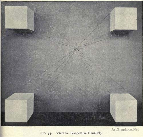
Fig. 34 is a perspective drawing of four cubes whose vertical faces are in two vertical planes, parallel to the picture plane. When naturally seen, this drawing does not give the appearance which any one cube presents to the eye at the station-point, but it does give the impression of four equal cubes, and of the facts of their positions, and it is the best drawing that can be made of the four cubes thus placed. If the drawing is viewed from a point opposite CV, and about 4" from the paper, the drawing of each cube will be foreshortened so as to create the same image in the eye as the cube it represents, but if the drawing is not thus seen, it is still the best drawing of the subject. The drawing is on a vertical picture plane, at right angles to the general direction in which the group of cubes is seen, and it illustrates the fact that When an object or a group of objects causing large visual angles is to be represented, a vertical picture plane, at right angles to a line to the centre of the group or the subject, must be used if the drawing is to give an idea of the facts of position and be satisfactory.
This is shown again by Figs. 35, 36, and 37. Fig. 35 is a perspective of a bureau, taken so as to give the appearance of inclination, which the horizontal lines of the drawer at the left must appear to have according to Rules 6 and 9. Fig. 36 is a perspective which, in the same way, gives the appearance of the drawer at the right. The left half of Fig. 35 is satisfactory if the right half is covered with paper, and the right half of Fig 36 is satisfactory if the left half is covered; but neither drawing gives a satisfactory impression of the whole bureau. To do this the perspective, Fig. 37, must be made on a plane at right angles to a horizontal line from the eye to a point over the centre of the bureau. These drawings illustrate the point shown also by Figs. 32 and 34, that the picture plane must be parallel to parallel straight lines which extend on both sides of the spectator if they are to be satisfactorily represented.
The station-point for Fig. 35 is about 3 1/2' from the paper and opposite a point near the top of the cut and over the left drawer. If seen from this point, the drawing is foreshortened by having its left side nearer the eye than its right, and will not appear distorted.
The station-point for Fig. 36 is about 3 1/2" from the paper and opposite a point near the top of the cut and, over the right drawer. If seen from this point, the drawing is foreshortened by having its right side nearer the eye than its left, and will not appear distorted.
 We find that the artist draws single objects just as he sees them, or, rather, feels them, and that. these drawings are generally satisfactory.; but sometimes single objects cannot be represented satisfactorily just as they appear. We find that the artist draws single objects just as he sees them, or, rather, feels them, and that. these drawings are generally satisfactory.; but sometimes single objects cannot be represented satisfactorily just as they appear.
Fig. 38 is a perspective taken upon a vertical plane perpendicular to a line from the eye to a point just over the centre of the object. It is not a satisfactory drawing of a right prism, for it gives the idea of a block whose nearer end is not at right angles to the long edges.
Fig. 39 is a perspective drawing upon a plane parallel to the long edges, and is much more satisfactory than Fig. 38, although most of Fig. 38 is like the appearance, and most of Fig. 39 is unlike the appearance. If a piece of paper is held to cover the left-hand line of Fig. 38, the rest of the drawing will be satisfactory, while in Fig. 39 the larger part is different from what the eye sees, but necessarily so in order that the effect of an oblique prism is not produced.
If pupils have a single object to draw, and one end appears a vertical line, as in Fig. 38, they should, if possible, move so that this end becomes visible, and the drawing, Fig. 4o, a satisfactory representation of the object, or so that the eye is between the two ends of the object, in which case the long lines would, as previously explained, be represented by horizontal lines, as in Figs. 32, 34, and 37. These drawings illustrate the following rules:
Rule 31. Whenever a vertical surface of a horizontal object is seen edgewise and appears a vertical line, any horizontal lines perpendicular to this surface must be represented by parallel horizontal lines.
Rule 32. Parallel horizontal lines connecting two vertical parallel surfaces, one at the right and the other at the left, must be represented by parallel horizontal lines ; that is, when only one of the vertical faces of a horizontal prism is visible from any point between the ends of this surface, the horizontal lines of this and parallel surfaces must be represented by horizontal lines.
Rule 33. When any two vertical surfaces at right angles to each other are visible as surfaces at the same time, the horizontal lines of both must appear to vanish.

Fig 38. An Unsatisfactory Drawing.
Fig 39. A Satisfactory Drawing.
Fig 40. Satisfactory.
Rule 34. Any drawing representing by the use of two vanishing points, two systems of lines at right angles to each other, must always be placed between the two vanishing points.
Rule 35. Any drawing representing by the use of two vanishing points, two systems of lines at right angles to each other, and which extends to or beyond either vanishing point, must be distorted.
The principles explained above should govern the representation of any subject of a geometric nature, without regard to the size of the subject, which is of no consequence, as the only point to be considered is the visual angle formed by the subject ; but to show how the rules apply to interiors and exteriors, the following illustrations are given.

Fig. 41 is a perspective representing one wall of a room which vanishes to the right. The lines perpendicular to the wall vanish at point CV in AB ; therefOre; the drawing is unsatisfactory, for all at the left of AB is outside of both vanishing points, and most unpleasantly distorted. Fig. 36 shows the same distortion in the left part of the bureau. The station-point from which Fig. 41 will not appear distorted is about 2 from CV
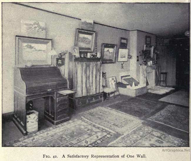
If this wall is to be represented by converging lines, the station- point must be about opposite the end of the room, and nothing at the left of the left vanishing point can be shown. Fig. 42 represents the wall when thus seen and is a satisfactory drawing. Like any perspective it requires, however, to produce the same image as the object, to be seen from the station-point, which is about 2 7/8" from the centre of the picture. When viewed naturally the perspective is unpleasant though not distorted as in Fig. 41.
The wall may be represented as seen from a station-point about opposite the centre of the wall. The resulting drawing, Fig. 43, is satisfactory, though, as already shown, it does not represent the appearance of the objects in the room unless the eye is at the station- point, which, in Fig. 43, is about 3" from the paper, and opposite point CV It gives, however, the positions of the objects with reference to the wall, and is often the best representation that can be made.

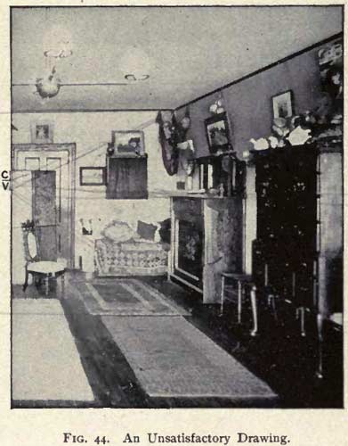
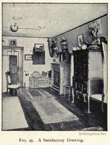
Fig. 44 represents two walls of a room as they are often illustrated. The drawing is unsatisfactory because it distorts the objects at the centre of the picture. The station-point for this drawing is about 3 1/2" from CV There is no reason why these objects should be distorted, and if the picture plane is placed at right angles to a horizontal line from the eye to the centre of the subject, both walls will be at angles to the picture plane and their lines will vanish as in Fig. 45. The station-point for Fig. 45 is about 3 1/2" from the centre of the picture, and this figure illustrates the following rule :
Rule 36. When two walls of a room are to be represented about equally, the drawing should have two vanishing points for the horizontal lines of the walls and lines parallel to the walls.
Fig 46 represents three walls of a room, the picture plane being at right angles to a line from the eye to the centre of the subject. As the eye is nearer the wall at the left than that at the right, the horizontal lines of the end of the room are at an angle to the picture plane, and vanish to the right. The lines of the other walls vanish at point CV in AB, and the drawing is very unsatisfactory, for all at the left of AB is distorted. If Fig. 46 is viewed from a station- point opposite CV and about 3" from the paper it will not appear distorted.
Fig. 47 is a perspective drawing on a plane parallel to the end of the room. It is the best drawing that can be made, and illustrates Rule 32 ; its station-point is about 3" from the centre of the picture.
In drawing interiors the artist will generally represent the actual visual proportions of his subject as far as this can be done by representing straight lines by straight lines, but he will always give the actual appearance of separate objects and details of the subject, unless it is necessary to show the positions of these objects with reference to the principal lines of the room. When furniture or other details have their lines parallel to those of the walls, the artist is obliged to make practically the exact parallel perspective drawing illustrated by Figs. 34, 37, 43, and 47. The artist may sometimes depart from the proportions of these parallel perspective drawings and give the foreshortening seen in horizontal and vertical dimensions, but when subjects similar to those mentioned above are to be represented, it is generally-best to make the exact perspective drawing which requires to be seen from one fixed point.
This is true, however, only with regard to geometric subjects, for the artist always represents other subjects just as he sees them. In figure drawing, for instance, he draws each figure just as he sees it, and would never think of making a scientific perspective drawing of such a subject as the Lord's Supper, except as regards the room.

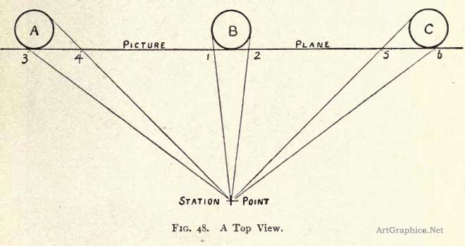
Fig. 48 is a top view representing the station-point or eye of a spectator who stands in front of the central cylinder, B, of a row of three equal cylinders, A, B; and C, and traces upon a vertical picture plane placed against the cylinders lines to cover each cylinder and form the perspective of the cylinders ; the cylinders may roughly represent three equal figures. The visual rays from A and B to the station-point pass through the picture plane obliquely, and thus the widths 3-4 and 5-6 of the drawings of A and C are wider than I-2 which represents the central figure. To make a scientific perspective, then, of figures arranged as in the Lord's Supper, the figures at the extremes of the canvas should be represented as much stouter or wider than those at the centre, in order that they will appear the same size as those at the centre when they are foreshortened by being seen obliquely by the eye situated at the station-point ; and this no artist would think of doing, for he always draws what he sees, and represents each figure so that it will look right when seen from a point directly in front of it.
When drawing exteriors and outdoor subjects, the principles governing the representation of objects and interiors should, with few exceptions, be applied. If the eye is opposite or very near one end or side of a large building of which one side only is seen, this side may be represented by vanishing lines, as in Fig. 42, but never so as to distort, as Fig. 41 distorts the desk. If the eye is situated as in Fig. 41, or is near the centre of the side to be represented, the horizontal lines of the side must be represented by horizontal lines, as in Fig. 43. If two vertical sides of a rectangular building are seen, the horizontal lines of both must vanish.
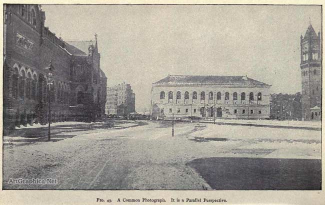
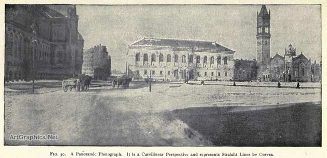
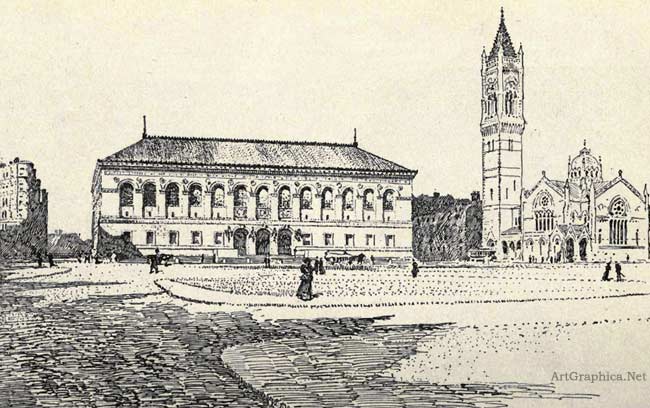
Fig 51. The best representation of the library.
When drawing a landscape, the artist will represent just what he sees and obtain a satisfactory picture, unless there are long straight lines, or straight lines causing large visual angles in the subject. In this case, if the artist draws what he sees, he will, as already shown, represent the straight lines by curved lines, and generally produce an unsatisfactory drawing.
In drawing an ordinary landscape or street scene, if the artist draws just what he sees, as he looks at the different parts of the subject, he is really making a drawing upon what is practically the vertical surface of a hollow cylinder ; for his subject has so little height in comparison with its width, that a vertical picture plane at right angles to the direction in which any part is seen will give practically a true picture of this part. As the artist turns, this vertical picture plane will sweep through a cylindrical surface, and an artist's drawing of an outdoor subject taking in a wide visual angle is practically the development of the surface of the cylinder upon which true pictures of the different parts are obtained. A drawing upon a cylindrical surface is called a cylindrical perspective, and represents parallel straight lines by curved lines which converge at opposite points.
A drawing which represents straight lines by curves is generally unsatisfactory. In some cases it may not be objectionable, and drawings of this nature have been made by noted artists. The student should never be allowed to make such a drawing, and the artist should do so only when the straight lines are frequently broken, or in different planes, so that it is not evident, at first glance, that the lines are straight and parallel. The same effect of curvature is produced by long vertical lines as by long parallel horizontal lines ; the artist may represent this convergence in the verticals, though not as often as he may represent the curvature of horizontal lines.
Fig. 49 is a curvilinear perspective which was taken with a revolving camera upon a cylindrical negative. It represents the Boston Public Library, with the Art Museum at the left and the New Old South Church at the right.
Fig. 50 represents the same subject by a common plane perspective drawing, which gives the idea of a straight street. From Fig. 49 we get the idea of a curved street and building. Fig. 5o is far preferable, and the artist should always represent straight lines by straight lines, unless the conditions are such that the effect of curvature is not noticeable or unpleasant ; but this is a question for the artist, the teacher and student should always represent straight lines by straight lines.
Although Fig. so is preferable to rig. 49, it distorts the parts at the right and left very unpleasantly, and the artist who wishes to represent the Library should omit the Art Museum, so as to be able to represent the Library and Church as they appear and by the use of two vanishing points. Fig. 51 shows how the artist may combine the horizontal dimensions of the curvilinear perspective, Fig. 49, with the straight lines of a plane perspective to produce the most satisfactory representation of the subject.
It is evident that any drawing, whether a scientific or a free-hand perspective, should be seen from a certain distance and point in order to produce the best effect. In drawings of single objects this point is generally outside the scientific perspective, so that the drawing is distorted when it is seen naturally. Of course, a freehand perspective may be distorted by being seen obliquely ; but drawings are naturally viewed perpendicularly, so that it requires an effort to view a free-hand perspective incorrectly, while the effort is required to see the scientific perspective correctly.
The free-hand perspective causes practically the same image in the eye whatever the distance be from which it is viewed, and when it is not seen from the proper station-point the impression received from it differs from that received from the objects only in regard to the relative sizes of the objects it represents.' When a scientific perspective is not seen from its station-point there is not only this change in the relative sizes of the objects, but also changes in their appearances; so every consideration favors the use of the free-hand perspective instead of the scientific.
It has been shown that the artist's drawing is not a drawing which can be made upon any plane, whatever its position. Another point
of difference between the artist's drawing and any perspective is due to the fact that a perspective represents what is seen by one eye, or from one fixed point, while the artist's drawing represents the facts of form realized by means of two eyes, that is, two station-points. The difference between a perspective and what is seen with both eyes will be readily appreciated by looking at any subject containing objects at different distances, first with one eye, then with the other, and then with both at once. By means of our two eyes we appreciate the roundness or solidity of objects and also their distances apart. These are the qualities which are most important to the artist, and it will be readily seen that his drawing must be a matter of feeling and not of science.
The pupil who uses the glass slate, except in work from copies, must close one eye to test accurately, and his drawing is thus a perspective. But this work is elementary, and necessary to prepare the pupil to see accurately enough to draw with feeling in later work when the slate is not used, and it gives the best preparatory education that can be obtained.
We must decide that the teacher should adopt the artist's methods, and enable pupils to draw first what the eye sees, -- that is, what will give the best impression of the appearance and the facts of single objects or subjects causing small visual angles, -- and then to teach them to apply perspective principles, as they may be needed to correct the drawings made by eye from geometric subjects causing wide visual angles, and finally to teach them the principles of scientific perspective, so that when this drawing is required, as it often will be, they may be able to produce it. But the teacher or student of perspective is not wise to insist that the artist shall always make scientific perspective drawings ; for he does not do this, and never will in his highest work, and we must accept the uniform practice of all great artists of the past and present to decide the point that it is not best to make, unless compelled to, a scientific perspective drawing which requires to be seen from one fixed point.
PREVIOUS PAGE
|


 We find that the artist draws single objects just as he sees them, or, rather, feels them, and that. these drawings are generally satisfactory.; but sometimes single objects cannot be represented satisfactorily just as they appear.


